Computer Simulation of the Hydraulic Control System for Exoskeleton
|
||||||||||||||||||||||||||||||||||||||||||||||||||||||||||||||||||||||||||||||||||||||||||||||||||||||||||||||||||||||||||||||||||||||||||||||||
|
|
Torque for actuator weight estimation (Nm) |
Unit weight (kg) |
No. of parts |
|
|
Weight of actuator @ shoulder |
296.1 |
10.00 |
2 |
20.00 |
|
Weight of link from shoulder to elbow |
- |
4.29 |
2 |
8.58 |
|
Weight of actuator @ elbow |
164.4 |
6.00 |
2 |
12.00 |
|
Weight of link from elbow to wrist |
- |
2.16 |
2 |
4.32 |
|
Weight of actuator @ wrist |
- |
3.00 |
2 |
6.00 |
|
Weight of hand |
- |
3.00 |
2 |
6.00 |
|
Weight of supporting bracket @ back |
- |
5.61 |
1 |
5.61 |
|
Weight of components @ back |
- |
20.00 |
1 |
20.00 |
|
Weight of actuator @ hip |
403.8 |
15.00 |
2 |
30.00 |
|
Weight of link from hip to knee cap (thigh) |
- |
4.67 |
2 |
9.34 |
|
Weight of actuator @ knee |
370.1 |
12.00 |
2 |
24.00 |
|
Weight of link from knee cap to ankle (calf) |
- |
4.39 |
2 |
8.78 |
|
Weight of actuator @ ankle |
370.1 |
12.00 |
2 |
24.00 |
|
Weight of foot |
- |
2.50 |
2 |
5.00 |
|
|
|
|
|
|
|
Weight of exoskeleton (kg) |
183.63 |
|||
Hydraulic
Power Pack
Hydraulic power pack includes a pump with
pressure regulator. Continuous flow of pressurized fluid at set pressure is
supplied by the pump. Energy characteristics of the hydraulic system with pump
with pressure control is shown in Fig.5a.
In Fig.4a, the basic diagram of the pump
with a pressure-control valve, manufactured by Rexroth A10 VSODR, is presented.
For the improvement of dimensional characteristics and configuration of a
hydraulic drive, and also with the purpose of improvement of thermal balance,
it is better to place the pump in a tank with a working fluid (Fig.6).
As flow control equipment, servo
directional valve, which are widely used in robotics and aerospace, are
considered. They have relatively small dimensions approximately 80х46х80 mm and
mass ~ 0.64kg, with high dynamic characteristics.
Electric-hydraulic amplifiers (servo
valves) with the mechanical feedback have wide
applications in hydraulic actuators. A
schematic diagram of a servo valve is shown in Fig.7,8. The servo valve
represents a combination of electromechanical converter (EMC) (1), the
hydraulic amplifier of a jet-flapper type (2) and a spool, which is connected
with the flapper by elastic feedback rod. Jet and flapper together represent an
adjustable throttle, resistance of which can be changed by changing the
distance between jet and flapper.
When an electric signal is applied to EMC,
an electromagnetic force is developed and this in turn rotates the armature
core. The angle of rotation depends on the level of input voltage. Along with
the armature, the flapper and the feedback spring also rotate, thus changing
the distance between the flapper and the jet. Due to this, the resistance of
adjustable throttles changes resulting in a pressure differential at the end
faces of the spool (3). This pressure differential causes the spool to move
from its neutral position, thus opening the flow ports of the spool casing, to
allow fluid flow. The movement of spool continues till the moment from the
feedback rod becomes equal to the electromagnetic moment of the armature. Thus
a constant flow of fluid through the valve is maintained as long as the input electric
signal is maintained constant. The flow is proportional to the input electric
signal. Fig.7,8 shows the Electric Hydraulic Amplifier (EHA) stage.
Since each part of exoskeleton requires
independent motion, they need to be controlled individually with dedicated
control valves and control strategy. The proposed hydraulic circuit diagram for
the exoskeleton (for 3 joints) is shown
in Fig.9. It includes the power
pack, hydraulic cylinders, and servo valves.
Estimated weight of elements of
various elements of the proposed 10 d.o.f. exoskeleton is given in Table №2.
Table №2
|
Actuator
name |
Weight of Cylinder,
kg |
Weight of servo-valve and manifold, kg |
Weight of pump and tank, kg |
Actuator weight оf exoskeleton |
|
Knee |
2.02 |
2.64 |
- |
|
|
Hip |
2.06 |
2.64 |
- |
|
|
Ankle |
1.71 |
2.64 |
- |
|
|
Shoulder |
1.91 |
2.64 |
- |
|
|
Elbow |
2.132 |
2.64 |
- |
|
|
Overall
weight |
9.832x2=19.664 |
13.2x2=26.4 |
8+10=18 |
64.1 |
The total weight of the hydraulic drive of
exoskeleton, without taking into account the weight of pipelines, is equal
~64.1kg, which is 46kg less than that of rotary hydraulic actuators.
2.
Mathematical model of hydraulic control system for exoskeleton
2.1.
Electric-hydraulic amplifier (servo valve) (Fig.8)
The equation of voltage in electric circuit
of electromagnet:
 , (2.1)
where ![]() voltage on the output of electronic amplifier;
voltage on the output of electronic amplifier; ![]() active resistance of a control coil of electromagnet;
active resistance of a control coil of electromagnet; ![]() inductance of a coil of electromagnet;
inductance of a coil of electromagnet; ![]() coefficient of back EMF;
coefficient of back EMF; ![]() electric
current in control coil;
electric
current in control coil; ![]() angle of flapper and an anchor of electromagnet, rigidly
connected to it.
angle of flapper and an anchor of electromagnet, rigidly
connected to it.
Value of
coefficient of back EMF is determined according to the following
ratio
 , (2.2)
where ![]() length of the average line of anchor;
length of the average line of anchor; ![]() ;
; ![]() air backlash
between the anchor and the feedback rod.
air backlash
between the anchor and the feedback rod.
The equation of motion of the armature with
flapper
 (2.3)
(2.3)
where ![]() moment
of inertia of armature;
moment
of inertia of armature; ![]() coefficient of a viscous amortization of armature;
coefficient of a viscous amortization of armature; ![]() moment of the hydro-dynamical force
moment of the hydro-dynamical force ![]() ,
, ![]() force of electromagnet;
force of electromagnet; ![]() rigidity of a spring of flapper,
rigidity of a spring of flapper,
![]() .
.
![]() , where
, where ![]() force, bending a feedback rod in the time of flapper
angle and spool displacement.
force, bending a feedback rod in the time of flapper
angle and spool displacement.
 , where
 ![]() module of elasticity of the material, of which the
feedback rod is made,
module of elasticity of the material, of which the
feedback rod is made, ![]() moment of inertia of the section of feedback rod
relatively of the main central
axis, perpendicular to the plane of bending force,
moment of inertia of the section of feedback rod
relatively of the main central
axis, perpendicular to the plane of bending force, ![]() deflection of
the end of feedback rod - is
equal to the sum of the deflections caused by the turn of the flapper
relatively of the center O on the angle
deflection of
the end of feedback rod - is
equal to the sum of the deflections caused by the turn of the flapper
relatively of the center O on the angle ![]() and displacement of
and displacement of ![]() of the spool,
of the spool,
![]() .
.
Equation of consumption of working liquid
in the control cascade:
 , (2.4)
where ![]() consumption of working fluid, providing
control of the main spool;
consumption of working fluid, providing
control of the main spool; ![]() square area
of the end face of spool of the main
spool;
square area
of the end face of spool of the main
spool; ![]() displacement
of the spool of the main spool;
displacement
of the spool of the main spool;  coefficient,
which is taking into
account the compressibility of a working
fluid in the face chambers of the main spool;
coefficient,
which is taking into
account the compressibility of a working
fluid in the face chambers of the main spool; ![]() volume of the face chamber of a spool;
volume of the face chamber of a spool; ![]() module
of volumetric elasticity of a working liquid;
module
of volumetric elasticity of a working liquid; ![]() pressure
of liquid in the control chambers under
the end faces of spool of the main
spool.
pressure
of liquid in the control chambers under
the end faces of spool of the main
spool.
Consumption ![]() is defined by known ratios from hydraulics:
is defined by known ratios from hydraulics:
![]()
![]() ,
,
where  conductivity
of a throttle of the servo valve;
conductivity
of a throttle of the servo valve; ![]() pressure of
the pump;
pressure of
the pump; ![]() coefficient of consumption of
liquid through the throttle;
coefficient of consumption of
liquid through the throttle; ![]() square area of the throttle,
square area of the throttle, ![]() specific conductivity of the
jet at neutral position of a flapper,
specific conductivity of the
jet at neutral position of a flapper,
 ,
, ![]() function,
determining the through passage section between the end face of jet and a
flapper,
function,
determining the through passage section between the end face of jet and a
flapper, ![]() displacement of a flapper,
displacement of a flapper, ![]() distance
between the jet and the flapper at neutral position.
distance
between the jet and the flapper at neutral position.
Equation
of the spool motion in hydraulic amplifier (servo valve)
 (2.5)
(2.5)
where ![]() mass of
the spool;
mass of
the spool; ![]() coefficient which is taking into account a
viscous friction in a backlash between the spool and a sleeve;
coefficient which is taking into account a
viscous friction in a backlash between the spool and a sleeve; ![]() rigidity of the spring of the main spool;
rigidity of the spring of the main spool; ![]() the hydro-dynamical force acting on the
spool of the main spool from the side of
working fluid;
the hydro-dynamical force acting on the
spool of the main spool from the side of
working fluid; ![]() force of viscous friction acting on the spool of the main spool;
force of viscous friction acting on the spool of the main spool; ![]() pressure
difference of working liquid at the end faces of the spool of the main spool;
pressure
difference of working liquid at the end faces of the spool of the main spool; ![]() the square area of the end face of the spool
of the servo valve.
the square area of the end face of the spool
of the servo valve.
Equation of consumption of fluid through
the main spool


where ![]() coefficient of consumption of the spool
window(hole);
coefficient of consumption of the spool
window(hole); ![]() diameter of spool of the main spool;
diameter of spool of the main spool; ![]() displacement
of the spool;
displacement
of the spool; ![]() coefficient
of overlapping of a spool
sleeve;
coefficient
of overlapping of a spool
sleeve; ![]() pressure of the pump;
pressure of the pump; ![]() pressure in the cavities of hydraulic
cylinder.
pressure in the cavities of hydraulic
cylinder.
Equation of pressures in the cavities
of hydraulic actuator
 (2.6)
(2.6)
Here ![]() the square area of the piston of hydraulic
actuator,
the square area of the piston of hydraulic
actuator, ![]() -
elasticity of a working liquid,
-
elasticity of a working liquid, ![]() -
volume of a liquid under the end face of the piston of a hydraulic actuator,
-
volume of a liquid under the end face of the piston of a hydraulic actuator, ![]() -
factor of compressibility of a working fluid.
-
factor of compressibility of a working fluid.
2.2. Hydraulic actuator (hydraulic
cylinder)
 , (3.1)
where ![]() the mass of the link, attached to a
hydraulic cylinder,
the mass of the link, attached to a
hydraulic cylinder, ![]() displacement of the piston rod of a hydraulic cylinder,
displacement of the piston rod of a hydraulic cylinder, ![]() coefficient
of friction of hydraulic
cylinder,
coefficient
of friction of hydraulic
cylinder, ![]() pressure in the cavities of a hydraulic cylinder,
pressure in the cavities of a hydraulic cylinder, ![]() external force applied to the piston rod of
hydraulic cylinder.
external force applied to the piston rod of
hydraulic cylinder.
2.3. The pump
with regulator of pressure
Diagram of the pump with a
regulator of pressure is given on fig 4a, 4c. Volume flow of the pump ![]() is determined by the following ratio:
is determined by the following ratio:
![]() , (4.1)
, (4.1)
where ![]() displacement
of the pump;
displacement
of the pump; ![]() maximal angle of swashplate turn;
maximal angle of swashplate turn; ![]() angular
speed of rotation of a shaft of the pump;
angular
speed of rotation of a shaft of the pump; ![]() current value of the angle of turn of the pump
swashplate.
current value of the angle of turn of the pump
swashplate.
Dependence between the displacements of the
piston of the control hydraulic cylinder and the angle of inclination of the
pump swashplate is defined by a expression:
 , (4.2)
where ![]() coordinate,
determining the position of piston of the hydraulic cylinder;
coordinate,
determining the position of piston of the hydraulic cylinder; ![]() maximal
value, which
maximal
value, which ![]() may
accept;
may
accept; ![]() radius of
the basic swashplate of the pump.
radius of
the basic swashplate of the pump.
We consider the pipelines, which connect
the pump with the hydraulic cylinders, short enough, so that we could consider
processes in them without taking into account distribution of parameters of a
working environment along the length of a hydraulic line. Then, proceeding from
the condition of incompressibility of fluid, the equation of consumption in the
pressure head hydraulic line can be written as follows:
 (4.3)
(4.3)
where ![]() volumetric
flow of the pump,
volumetric
flow of the pump, ![]() consumption, required for functioning of the
hydraulic drives;
consumption, required for functioning of the
hydraulic drives; ![]() flow
rate of the liquid going for
control;
flow
rate of the liquid going for
control; ![]() coefficient, which is taking into account a compressibility of a
working liquid in the pipelines;
coefficient, which is taking into account a compressibility of a
working liquid in the pipelines; ![]() pressure of
the pump.
pressure of
the pump.
Consumption of fluid, necessary for the
operation of hydraulic drives:
 (4.4)
(4.4)
where ![]() flow rate of liquid, consumed by
flow rate of liquid, consumed by ![]() hydraulic drive;
hydraulic drive; ![]() number of
hydraulic drives connected to the pump.
number of
hydraulic drives connected to the pump.
Equation
of motion of the spool of pressure regulator
![]() (4.5)
(4.5)
where ![]() mass of the
spool and of the mobile parts of the pressure regulator spool, attached to it;
mass of the
spool and of the mobile parts of the pressure regulator spool, attached to it; ![]() displacement
of the pressure compensator spool;
displacement
of the pressure compensator spool; ![]() coefficient, which is taking into account the viscous friction in
a backlash between the spool and a sleeve;
coefficient, which is taking into account the viscous friction in
a backlash between the spool and a sleeve; ![]() rigidity of the spring of pressure
compensator;
rigidity of the spring of pressure
compensator; ![]() force of the
preliminary compression of the spring;
force of the
preliminary compression of the spring; ![]() hydro-dynamical
force, acting on the spool from working fluid;
hydro-dynamical
force, acting on the spool from working fluid; ![]() square area of the end face of the pressure
compensator spool.
square area of the end face of the pressure
compensator spool.
Equation
of motion of the pump swashplate and of the control hydraulic
cylinder
![]() (4.6)
(4.6)
where ![]() mass of piston of the control cylinder and
attached to it mobile parts of the mechanism of adjustment of pump flow;
mass of piston of the control cylinder and
attached to it mobile parts of the mechanism of adjustment of pump flow; ![]() coefficients of viscous
friction in the backlashes between the
pistons and the sleeves of the control cylinders;
coefficients of viscous
friction in the backlashes between the
pistons and the sleeves of the control cylinders; ![]() rigidity of
the spring of control cylinder;
rigidity of
the spring of control cylinder; ![]() force of the
preliminary compression of the spring;
force of the
preliminary compression of the spring; ![]() square
areas of piston of the control
hydraulic cylinders;
square
areas of piston of the control
hydraulic cylinders; ![]() total moment
of resistance, applied to the regulating element of the pump,
total moment
of resistance, applied to the regulating element of the pump, ![]() displacement
of the
rod of the control hydraulic cylinder,
displacement
of the
rod of the control hydraulic cylinder, ![]() pressure in
the cavity of the control cylinder.
pressure in
the cavity of the control cylinder.
Pressure in cavity of control cylinder
If y
< 0.5 xогд. max
 - Pressure in control cylinder.

If y > 0.5 xогд. max

 - flow through the spool of pressure
regulator.
- flow through the spool of pressure
regulator.
2.4.
Structure of control system (fig.10)
All servo
valves and hydraulic cylinders
are incorporated into a united control system. On this slide the control system
for one hydraulic cylinder is shown.
The
specifying signal from a top level control system and signal from the gauge of
a feedback of the hydraulic cylinder enter to summation device. Feedback signal
has an opposite sign.
Further the signal enters on input of servo
valve amplifier. Resulting signal acts on the coils of servo valve magnet.
Displacement of a spool corresponds to a level of a signal which enters on an
input of servo valve.
The flow of a working fluid and speed of
cylinder accordingly, depends on displacement of a spool of servo valve.
3. Results of modeling
Each leg of exoskeleton has three active
degrees of freedom. Accordingly, three executive hydraulic cylinders should
drive one leg; also three servo valves are required. Two hydraulic cylinders
are required to actuate one hand, and two electric-hydraulic amplifiers
(directional servo valve) to control them. Thus, exoskeleton includes 10
hydraulic cylinders. All of them are powered from one pump.
The system of equations, describing the
functioning of the hydraulic drives for two legs, two hands and the pump with
the pressure regulator, represents the system of the ordinary differential
equations (ODE) of the order of 116, written down in normal form of Cauchy. For
the decision of the ODE system, a Runge-Kutta method of integration, in the
modification of Merson was used.
For the definition of adequacy of the
composed mathematical models of the elements, which are included in the
hydraulic drive, a mathematical modeling of the separate elements was carried
out, in particular, - servo valve. Characteristics of servo valves, designed by
the Rexroth company are given in Fig.11, which represent the reaction of servo
valves to a step input electric signal at various values of pressure.
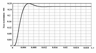
In Fig.12, a similar characteristic,
obtained from modeling of servo valves, is presented. A stepping signal was
applied to the input of servo valves. Supply pressure was set at 210bar.
It is visible from the results that the
simulated performance of the servo valve is similar to the valve
characteristics presented in the manufacturers catalogue.
The program for modeling a hydraulic
control system of exoskeleton allows setting an input voltage as step input or
a sinusoidal signal.
The torque loads acting on the various
joints have been calculated and are presented in Table №1. Proceeding from the
geometrical sizes of parts of exoskeleton, the forces, acting on the hydraulic
cylinders, were determined. Based on the assumptions that these values of
torques are the maximum, joint positions, where maximum torque is acting, were determined.
For the legs, it is a position when the angle in the knee joint is equal to
90°.
In Fig.13-23, results of modeling of
operation of the hydraulic drive of exoskeleton are given. Two modes of the
most typical motion of the human were chosen for modeling.
The first mode corresponds to the getting
up of the human from the semi-sitting position and a simultaneous rising of
hands. Motion is carried out from the position, where the knee joint is at 90°
w.r.t. the sheen bone, and the thigh bone is in a horizontal position. Final
position corresponds to the movement when the person is in vertical standing
position. Such motion is typical for the human, when he is lifting the loads.
A sinusoidal type voltage was applied to
the input of each tracing drive. The period of a sinusoid corresponds to the
rising up of exoskeleton from the semi-sitting position for 1.5sec and a
knee-bend for the same period. The maximal loadings, acting on the hydraulic
cylinders, have been obtained from the values of twisting moments in each of
the joints, obtained at the Nanyang Technological University of Singapore.
Proceeding from the kinematic diagram of exoskeleton, in which hydraulic
cylinders are used as executive hydraulic actuators, loadings at each of the
joints have been obtained.
Table №3
|
The name of a link |
Value of the moment, Н*м |
Value of force, кН |
|
Knee |
370.1 |
2.96 |
|
Hip |
403.8 |
4.038 |
|
Shin |
370.1 |
2.96 |
|
Shoulder |
296.1 |
4.23 |
|
Elbow |
164.4 |
2.342 |
The loading, acting on the hydraulic cylinder, has a constant value.
Values of loadings are given in Table №3. While rising up, the hydraulic
cylinders belonging to the opposite sides of exoskeleton move in one phase with
identical speeds. Motions of the rods of hydraulic cylinders are limited to the
maximal values of displacements, obtained from the kinematic diagram of
exoskeleton.
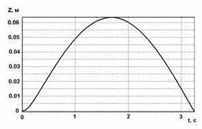
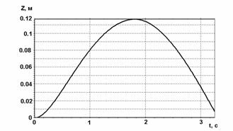
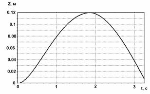
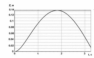
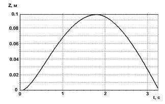
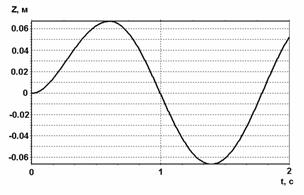
From the diagrams of displacements of the
hydraulic cylinders of the hip (Fig.15), knee (Fig.14), shins (Fig.13), elbow
(Fig.16), and shoulder (Fig.17), it is visible that hydraulic drives trace an
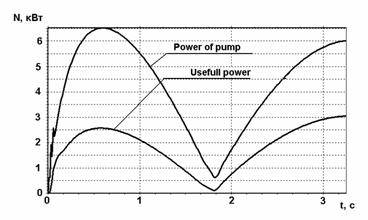
input signal. In Fig.18, the power of the pump and the useful power developed
by the hydraulic cylinders of all parts of exoskeleton are given. This diagram
characterizes the power efficiency of a hydraulic actuator. Apparently from the diagram, the efficiency of a hydraulic
drive averages 50% and higher, that for a hydraulic drive with throttle control
with pressure control pump is quite satisfactory.
The second mode of motion models the
walking of the human. At motion one leg is in a phase of a support, this phase
is characterized by the relatively high loadings and small speeds, the second
leg is in a phase of carry, which is characterized by the small loadings and
high speeds.
As there is no dependence between the
values of displacements of hydraulic cylinders and the loadings, applied to
them, we have chosen the sine wave law of change of loadings with the amplitude
equal to a maximal loading. The loadings acting on hydraulic cylinders, and
also their speeds may considerably differ at different modes of operation of exoskeleton.
As there are no data about the loading
arising in the joints of exoskeleton during walking, we have chosen, as loading
characteristics, a sine wave law of their change. The loading was changed on a
sinusoid with frequency 2Hz for hydraulic actuators of legs and frequency 1 Hz
for hydraulic actuators of hands. Amplitude of loadings in degrees of
freedom: knee - 1000N, shin - 1200N, hip
- 1500N, shoulder - 1000N, elbow - 1000N. Thus both the input signal and the
loadings, working on the same hydraulic cylinders and belonging to the opposite
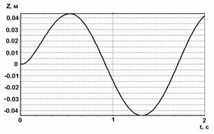
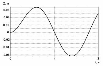
sides, change with a 180 degree phase shift. The results
of simulation show that the
hydraulic drive well traces input signals (Fig. 20-22). Displacements of
hydraulic cylinders, belonging to the opposite side, have the same kind of
diagrams, only with an opposite phase.
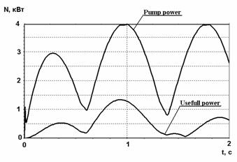
Power characteristics can be estimated
under the diagram of power of the pump and useful power (Fig.23). The
efficiency is on the average equal 30%. A mathematical modeling of the several
modes with various values of frequency and amplitude was carried out. For all
modes, the hydraulic drive well traces an input signal and has the efficiency
30-40%, that is a good value for a
hydraulic drive with the volume-throttle regulation. More precise results can
be obtained by knowing the loading characteristics for each joint of
exoskeleton.
Based on the results obtained from the
above analysis, it is possible to draw the following conclusions. The pump,
working at constant pressure, supports constant pressure in the system.
Therefore such pump may not provide high power characteristics in all range of
changes of working pressure of hydraulic drives of exoskeleton. It is visible
from the power characteristic given on fig 8. If the pressure in hydraulic
cylinders is close to the pressure of adjustment of the pump, then losses in
hydraulic system will be minimal as pressure losses in the servo valves will be
less. Thus, adjustment and control of the working pressure of the pump in
dependence of the mode of motion of exoskeleton, may improve power
characteristics of the hydraulic drive.
The regulator of pressure may change
working pressure of the pump in a range from 20 up to 210bar. It is provided by
the value of preliminary compression of the pressure limiting spool spring.
During the operation of exoskeleton, there is no accessibility to adjust the
value of spring compression and hence this has to be done through remote
control. The basic hydraulic diagram of such pump is given on Fig.4b.
For example, when exoskeleton overcomes
significant loadings and the high pressure is required in the hydraulic
cylinders, then the regulator of pressure should be adjusted to a high
pressure. Results of modeling of the first mode may serve as an example: when
exoskeleton rises up from a semi-sitting position with loading. During walking
with small loading, high pressure in hydraulic cylinders is not required, the
regulator may be adjusted to a smaller pressure and hence reduce losses of
pressure in servo valves. Thus, by adjusting the regulator pressure of the pump
with reference to the loading and mode of motion, it is possible to optimize
power characteristics.
As a signal for changing working pressure
of the pump may be used signal from the load detector installed at the any limb
of exoskeleton for example at back or at hip. Depending of the value of the
signal from detector it’s possible to define the loads which act on the
cylinders and depending on it install the pump working pressure.
In the whole the offered hydraulic system
provides the functioning of exoskeleton at various modes of operation.
List
of literature
1.
Borovin
G.K. Computer Simulation of Hydraulic Control System of the Walking Machine.
Proceedings 2nd Tampere Intern. Conference on Machine Automat, ICMA'98,
p.p. 179-192.
2.
Borovin
G.K. Computer Simulation of Hydraulic Control System of the Walking Machine.
Preprint KIAM RAS №106, М., 1995г. 28p.
(in russian)
3.
Borovin
G.K., Kostyuk A.V. Computer Simulation of Hydraulic Actuator with LS-control of
the Walking Machine. Preprint RIAM RAS
№54, М., 2001г. 28p.
(in russian)
4.
Borovin
G.K., Kostyuk A.V. Computer Simulation of Hydraulic System of the Walking
Machine. // Proceedings 11nd Conference «Extremal robotics»,
St-Petrsburg, StPSTU, 2001, p.p. 96-106. (in russian)
5.
Borovin
G.K., Kostyuk A.V. Computer Simulation of Hydraulic Control System of the
Walking Machine. // Proceedings Conference «Mobile robots and mechatronny
systems», Моscow, МSU,
december 2001, 15p. (in russian)
6.
Borovin
G.K., Kostyuk A.V. Computer Simulation of
Hydraulic Control System of the Walking Machine. //
Theory and control systems. 2002, №4. (in russian)
7.
Borovin
G.K., Kostyuk A.V. Computer Simulation of dynamics of Hydraulic Actuator of the Walking Machine. №8, М., 2002, 28p. (in russian)
8.
Manessmann
Rexroth, Brueninghaus Hydromatik. “Product Catalogue Axial Piston Units”, Horb,
Germany, 1997.
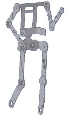
Fig 1. The
kinematic diagram of exoskeleton
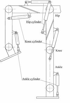
Fig 2. Kinematic diagram of leg of exoskeleton with
the use of hydraulic cylinders
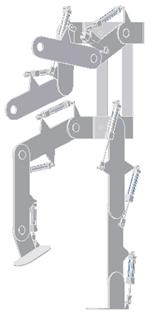
Fig. 2a. Kinematical diagram of exoskeleton with the
use of hydraulic cylinders (passive degrees of freedom are not shown)
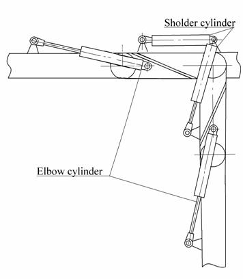
Fig 3. Kinematic diagram of a shoulder and a hand with
application of hydraulic cylinders
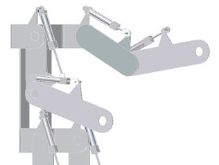
Fig. 3a. Kinematic diagram of the hands and shoulders
with application of hydraulic cylinders (passive degrees of freedom are not
shown)
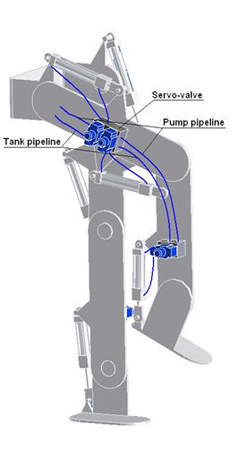
Fig 3b. Legs
of exoskeleton with servo valves and hydraulic cylinders
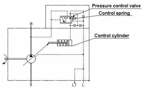
Fig.
4a. The basic hydraulic circuit of the pump with pressure control
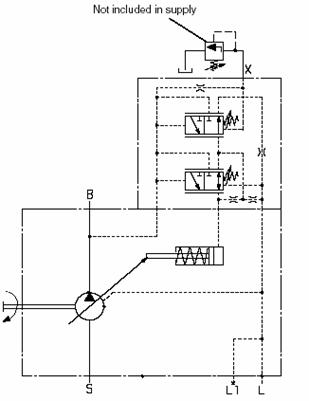
Fig. 4b. The basic hydraulic circuit of the pump with the
pressure regulator with remote
control
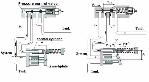
Fig. 4c. Scheme of the pump with
pressure regulator
Fig.5a. The characteristic of the hydraulic drive
working with pump with
pressure regulator

Fig. 5b. The characteristic of the pump working on
constant pressure
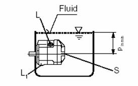
Fig. 6. The circuit of an arrangement of the pump
inside a tank
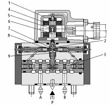
Fig. 7. The
electric-hydraulic amplifier of type (servo directional valve)
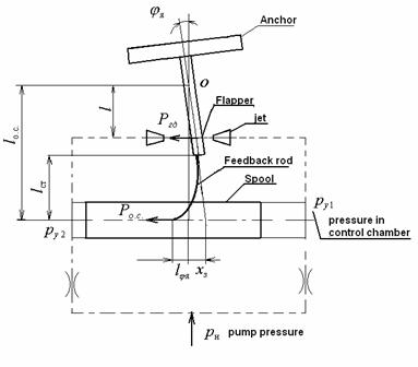
Fig. 8. The diagram for calculation of the electric-hydraulic
amplifier (servo valve) with a force feedback from a
spool to a flapper
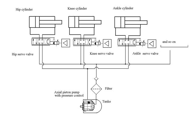
Fig 9. The basic hydraulic circuit of exoskeleton
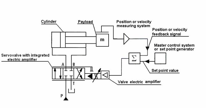
Fig.10. Diagram of hydraulic driver control system
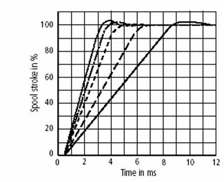
Fig 11. Characteristic of servo valve at step input
influence
|
Fig.12.
Diagram of displacement of the
Fig.13. Displacement of the shin
spool of servo valve at step hydraulic cylinder at
rising up
input influence and knee-bending of exoskeleton |
|
Fig.14. Displacement of the knee Fig.15. Displacement of
the hip hydraulic cylinder at rising up
and hydraulic
cylinder at rising up knee-bending of exoskeleton and knee-bending of exoskeleton |
|
Fig.16. Displacement
of the elbow Fig.17.
Displacement of a shoulder
hydraulic cylinder at raising and hydraulic cylinder at a
raising and
lowering of hands of exoskeleton lowering of hands of
exoskeleton
|
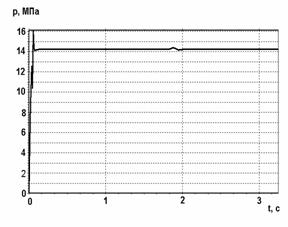
|
Fig.18. Diagrams of the power of the pump Fig.19. Diagram of pressure of the and useful power of all hydraulic pump cylinders |
|
Fig.20. Displacement of the hip Fig.21. The diagram of the
displacement hydraulic cylinder at walking of a shin
hydraulic cylinder at walking |
|
Fig. 22. Displacement of a knee Fig.23. Diagrams of
power of the pump hydraulic cylinder at walking and useful power of the hydraulic
cylinders of exoskeleton |